


Views: 0 Author: Site Editor Publish Time: 2026-09-15 Origin: Site


The shift toward larger wafer sizes and N-type cell architectures has made busbar configuration a critical factor in module selection. Buyers evaluating modern panels must routinely balance peak power output against micro-crack vulnerability, module weight, and inverter compatibility. Making incorrect assumptions about these specifications frequently bottlenecks system performance. You might select a high-power panel only to discover it exceeds your inverter limits. Understanding how multi-busbar (MBB) and super-multi-busbar (SMBB) technologies dictate overall output helps you optimize the Levelized Cost of Energy (LCOE). You can precisely align hardware choices to specific project constraints. This comprehensive guide breaks down the physical differences between market-leading architectures. We will explore how these dense wire configurations influence real-world performance metrics. You will gain actionable frameworks to confidently select the right solar technology for your next residential, commercial, or utility-scale deployment.
A solar cell busbar acts as the primary conduit for direct current; increasing the count (from 10 to 16 or 18) reduces internal electrical resistance and mitigates power loss from micro-cracks.
The 10BB PERC Solar Cell remains a highly reliable, cost-effective baseline for residential and standard commercial deployments with strict upfront budget caps.
Upgrading to a 16BB M10 TOPCon Cell or 16BB G12R Cell offers the optimal balance of high power density, manageable module size, and broad inverter compatibility.
The 18BB G12 Cell maximizes yield for utility-scale projects but requires careful string inverter matching due to significantly higher operating currents.
A solar cell busbar functions as the primary highway for the direct current generated by your panels. Transitioning from traditional five-busbar formats to advanced super-multi-busbar designs changes fundamental module performance. It significantly shortens the physical distance electrons must travel across the silicon surface. This reduced distance directly lowers the internal series resistance of the panel. You immediately see less energy wasted as heat during peak sunlight hours. Lower resistance translates into higher overall panel efficiency.
Higher busbar density also delivers incredible micro-crack mitigation. Extensive field testing shows these dense wire networks create robust, redundant electrical pathways. If a solar cell suffers localized fracturing during transport, the panel continues to perform. The redundant matrix simply routes the electrical current around the damaged silicon area. Older panels would lose entire sections of power generation under similar stress. This resilience protects your long-term energy yields.
Manufacturers also benefit heavily from this density shift. You might assume more wires require more expensive raw materials. Industry realities prove otherwise. Advanced super-multi-busbar designs utilize ultra-thin round wire ribbons. These narrow ribbons significantly reduce expensive silver paste consumption during the manufacturing process. They also minimize optical shading compared to older, wider flat ribbons. Sunlight hits the round surface of the wire and reflects downward into the active silicon. This traps more light and further boosts energy production.
The 10BB PERC Solar Cell represents a highly mature, heavily verified solution in today's market. Manufacturers typically build this proven P-type technology on standard 182mm (M10) silicon wafers. It remains an industry workhorse for a very specific set of reasons.
It delivers an incredibly predictable performance baseline for system designers. You can reliably expect standard module efficiencies hovering between 20% and 21%. Decades of real-world field data back its established long-term degradation profiles. This verifiable reliability provides immense peace of mind for standard installations. Investors trust the data supporting these modules.
Residential rooftops and standard commercial C&I projects stand out as ideal use cases. When upfront CapEx strictly dictates your primary project constraint, this technology shines. It fits perfectly into budgets where ultra-high wattage per square meter is not strictly required. You get solid, reliable yield without paying a premium for cutting-edge internal architecture.
However, you must acknowledge its physical limitations. This configuration has a much lower efficiency ceiling than modern alternatives. It also exhibits higher temperature coefficients compared to newer N-type configurations. Power output drops more noticeably on extremely hot summer afternoons. We recommend accounting for these thermal losses during your initial site yield estimates.
Table 1: 10BB PERC Performance Summary
Feature | Standard Specification | Real-World Outcome |
|---|---|---|
Wafer Size | 182mm (M10) | Manageable module weight for residential roofs. |
Cell Technology | P-Type PERC | Predictable but slightly higher annual degradation. |
Efficiency Range | 20% - 21% | Excellent baseline performance for standard budgets. |
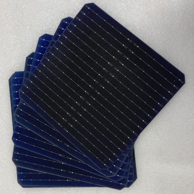
Advanced N-type cell architectures now dominate the commercial and industrial standard. Manufacturers heavily optimize these specific formats for container shipping and streamlined manual handling. They represent the current technological sweet spot.
The 16BB M10 TOPCon Cell perfectly illustrates this recent evolution. It pairs 16 ultra-thin micro-wires with advanced N-type TOPCon silicon layers. This specific chemical and physical combination drastically lowers electron recombination losses. Electrons flow smoothly across the cell surface, pushing module efficiencies comfortably beyond 22.5%. It gives you exceptional power density within a highly standardized physical footprint.
Alternatively, many developers now opt for the 16BB G12R Cell. This configuration utilizes a unique rectangular wafer format measuring 182mm by 210mm. This elongated shape maximizes packing density on standardized international shipping pallets. It fills standard 40-foot high-cube shipping containers perfectly. This geometry reduces logistics and freight costs significantly. At the same time, it keeps the physical module width entirely manageable. Installation crews can handle it manually without specialized lifting equipment. It also mounts cleanly and securely onto standard single-axis trackers.
Both formats carry a remarkably minimal risk profile regarding implementation. They operate safely within the standard input voltage and current limits of most modern string inverters. They also pair nicely with standard micro-inverters. You rarely need to purchase specialized, expensive balance-of-system equipment to accommodate them.
Utility-scale solar farms demand maximum land utilization and extreme power density. The industry engineered these ultra-large format modules specifically for massive ground-mount installations. You rarely see them on residential properties.
A massive 210mm square wafer generates an immense amount of direct current. Standard wiring matrices simply cannot handle this volume of electricity. This is exactly why the 18BB G12 Cell utilizes 18 distinct busbars. This incredibly dense layout effectively manages the high current generation. It prevents severe thermal losses across the silicon surface. It also drastically reduces the risk of localized hot spots forming over time.
When evaluating these ultra-large modules, you must look at the direct operational outcomes. You physically require fewer modules per megawatt installed on your site. This translates directly into substantial Balance of System (BOS) savings. You spend significantly less money on steel racking systems. You purchase miles less copper wiring. You require fewer combiner boxes. Most importantly, your crews spend fewer total hours mounting panels in the field.
However, you must respect the associated risks and physical realities. These large modules produce very high operating currents. They frequently exceed 17A or 18A under peak sunlight conditions. You must strictly verify your central or string inverter’s maximum input current specifications. Furthermore, increased module dimensions inherently increase overall panel weight and wind load. Your site engineers must specify highly robust mounting hardware. Proper structural support prevents catastrophic storm damage.
Selecting the correct solar panel involves much more than chasing peak wattage numbers. You must critically analyze your specific project constraints before ordering hardware.
Consider the ongoing debate between CapEx and Levelized Cost of Energy (LCOE). Cheaper legacy modules easily win on initial hardware cost. They keep upfront spending incredibly low. Yet, advanced N-type modules often deliver a vastly superior LCOE over a complete 25-year lifespan. They experience notably lower annual degradation. They also generate higher bifacial yields when mounted over reflective surfaces. You essentially harvest more total energy over the system's life.
Always execute a comprehensive compatibility audit before finalizing your purchase. Use this physical constraint checklist to guide your engineering team:
Inverter Matching: Verify maximum power current (Imp) and short-circuit current (Isc) ratings against strict 18BB limitations.
Physical Constraints: Assess structural weight limits on older residential roofs. These weight limits heavily favor smaller formats. Utility ground mounts easily support larger formats.
Environmental Factors: Note extreme high-temperature zones. N-type modules resist heat degradation far better than older P-type panels.
Wind Loading: Calculate localized wind speeds. Larger G12 modules catch more wind and require stronger clamping zones.
Take these actionable next steps to finalize your technology procurement safely:
Request detailed specification sheets (PAN files) directly from your shortlisted panel manufacturers.
Input these precise files into PVsyst or similar professional modeling software.
Run multiple simulations comparing real-world yield differences across the three technologies using your specific climate zone data.
Consult structural engineers to confirm racking compatibility for the larger rectangular modules.
Chart 1: Technology Application Matrix
Technology Format | Primary Constraint Solved | Best Application Environment |
|---|---|---|
10BB PERC (182mm) | Strict upfront budget limits | Residential rooftops, standard commercial |
16BB TOPCon (M10/G12R) | Space constraints & tracking | High-end residential, C&I tracking systems |
18BB TOPCon (G12) | Utility scale Balance of System costs | Large-scale ground mount solar farms |
More busbars do not automatically equate to a universally better panel for every scenario. The configuration choice must seamlessly align with cell size, system architecture, and budget parameters. Pushing a massive utility module onto a small residential roof creates complex installation nightmares. Conversely, installing older technology on a sprawling utility farm sacrifices substantial long-term yield.
We highly recommend defaulting to 16BB TOPCon for the widest applicability and future-proofing. It beautifully blends high efficiency, manageable physical dimensions, and incredibly broad inverter compatibility. Reserve older 10BB models strictly for deployments facing extreme budget constraints. Keep the massive 18BB architectures reserved strictly for engineered utility-scale power plants.
Always prompt your procurement team to consult closely with technical engineering divisions before finalizing a bulk purchase. Request a thorough technical sizing review based entirely on your specific site constraints. Proper upfront planning prevents expensive electrical bottlenecks in the field.
A: You can identify the count by examining a single solar cell on the panel. Look for the solid vertical metallic lines running from top to bottom. Count these primary lines across one distinct square cell. If you count 16 lines, you are looking at a 16BB panel.
A: No. Many assume extra processing makes the silicon weaker. The opposite is actually true. The dense, redundant wire matrix acts like a supportive net. It holds the silicon together tightly during transport. It actively prevents minor micro-cracks from expanding and isolating large sections of power generation.
A: Often, they will not. These massive cells generate significantly higher current levels than standard formats. Many existing micro-inverters will experience severe current clipping, completely wasting potential energy. Always rigorously check your inverter's maximum input current specification sheet before attempting to pair them with ultra-large modules.


